

Precision Plastic Injection Molding for High-Performance Automotive Parts
Plastic injection molding for automotive parts is a manufacturing process where melted plastic is forced into a steel mold to create durable, high-precision components like dashboards, bumpers, and interior trim. By allowing complex shapes to be formed in a single, rapid cycle, this method delivers consistent quality and strength while keeping weight low to improve fuel efficiency. It’s a straightforward way to produce everything from small clips to large body panels, making it a go-to technique for building cars that are both reliable and cost-effective.
Core Advantages of Manufacturing Vehicle Components via High-Pressure Molding
High-pressure molding delivers dimensional precision for complex geometries like engine bay connectors and sensor housings, holding tolerances within microns. This process ensures uniform wall thickness and eliminates internal voids, critical for parts that must withstand thermal cycling and vibration. The high packing pressure improves polymer crystallization, yielding components with superior impact resistance and reduced creep under load. Tooling designed for rapid heat transfer shortens cycle times, directly lowering per-part cost without sacrificing surface finish. You also achieve repeatable filling of thin-wall sections, which is essential for lightweighting strategies in modern vehicle structures while maintaining structural integrity.
Weight reduction strategies using advanced polymers
Advanced polymers enable targeted weight reduction in automotive parts by replacing metal components without sacrificing structural integrity. High-pressure molding facilitates thinner wall sections through precise cavity fill and consistent material density, directly reducing part mass. A clear sequence for implementation includes:
- Selecting a high-strength polymer composite, such as carbon-fiber-reinforced nylon, to replace a metallic equivalent.
- Employing high-pressure injection to allow thinner walls, lowering weight by up to 40%.
- Optimizing ribbed or honeycomb geometries in the mold to maintain stiffness while removing excess polymer.
This strategy delivers lighter vehicles, improving fuel efficiency and handling without requiring secondary assembly or joining processes.
Cost efficiency in high-volume production runs
Once the mold is built, cost efficiency in high-volume production runs drops dramatically per part, as the same tool churns out thousands of identical components with almost zero added labor. Economies of scale kick in hard here, spreading the initial six-figure tooling investment over millions of units until the per-piece cost becomes cents. Cycle times of 20–30 seconds keep the machine constantly spitting profit. This per-unit math only works if your order volume justifies the upfront mold spend, but when plastic injection molding automotive parts it does, the margin per part gets brutally lean.
| Aspect | High-Volume Effect |
| Tooling cost per part | Drops to near-zero after ~100,000 units |
| Labor per part | Negligible, as automation handles ejection |
| Material waste | Minimized through precise shot control |
Design flexibility for complex geometries
High-pressure injection molding enables complex geometry integration through precise melt flow control, allowing automotive parts like intake manifolds or sensor housings to incorporate internal channels, undercuts, and thin walls in a single tool. This flexibility eliminates multi-piece assembly, as designers can combine snap-fits, reinforcing ribs, and variable wall thicknesses directly into the mold geometry. The process supports intricate curvature and tight tolerances unreachable by machining, and allows for core pulls or lifters to form side actions without secondary operations.
Critical Material Selections for Automotive Applications
The mechanic’s grease-stained hands told the story of a dashboard that cracked after three winters. That failure traced back to a material selection prioritizing cost over UV stability and thermal cycling resistance. For automotive injection molding, polypropylene blends with talc fillers offer dimensional stability for interior trim, while glass-filled nylon 6/6 handles under-hood heat but demands careful mold temperature control to prevent warpage. Choosing between a PBT/PET blend and a high-heat ABS truly hinges on whether the part faces constant sun exposure or occasional oil mist. Every polymer choice directly dictates the part’s ability to survive vibration, creep from bolt torque, and the paradox of a freezing winter dash turning into a summer oven.
Thermoplastics versus thermosets for under-hood durability
For under-hood durability, thermoplastics like PPS or PA66 offer better impact resistance and recyclability, but they can creep or soften near the engine block. Thermosets, such as phenolic or BMC, excel in continuous high heat without deformation, though they’re brittle and cannot be reprocessed. Thermoplastics versus thermosets for under-hood durability often comes down to thermal load versus mechanical stress. Real-world testing reveals thermosets win for rigid mounts near exhaust, while thermoplastics survive better where vibration dampening is needed.
- Thermoplastics risk warping above 150°C, but thermosets handle 200°C+ without sagging.
- Thermosets fracture under sudden impacts; thermoplastics absorb shock by yielding.
- Under-hood chemical exposure favors thermosets for seal and gasket longevity.
Fiber-reinforced compounds for structural integrity
Fiber-reinforced compounds, typically using carbon or glass fibers in a polymer matrix, are selected for structural integrity in injection-molded automotive parts to achieve high stiffness-to-weight ratios. The fiber orientation within the mold flow directly dictates load-bearing capacity, requiring precise gating design to align fibers along stress vectors for maximum strength. Balancing fiber length against melt flowability is critical, as longer fibers enhance tensile modulus but increase viscosity and potential for breakage. This material choice enables thin-wall geometries that replace metal brackets and mounts, reducing mass without sacrificing crashworthiness. The selected compound must exhibit creep resistance under sustained loads, making short-fiber reinforced polyamide a frequent choice for under-hood structural components.
Flame-retardant and UV-stable formulations
Under-hood components and interior trims demand flame-retardant and UV-stable formulations that withstand prolonged thermal stress without degrading. In injection molding, brominated or phosphorus-based FR additives are compounded directly into polypropylene or ABS, while UV stabilizers like hindered amine light stabilizers (HALS) and carbon black prevent surface cracking from sun exposure. The challenge lies in balancing additive loadings: too much flame retardant can reduce impact strength, while insufficient UV protection causes color fading. Advanced masterbatch technologies allow precise dispersion, ensuring dashboard panels and connector housings pass both burn-rate tests and long-term sunlight resistance without secondary coatings. These tailored blends maintain dimensional stability through repeated heat cycles.

Precision Molding Techniques Enhancing Part Quality
On the factory floor, achieving flawless fit for an automotive dashboard trim demands more than just an accurate mold. Precision molding techniques like injection-compression allow the machine to gently form complex geometries, reducing internal stress that causes warping in extreme heat. By implementing closed-loop process control, the system continuously adjusts fill pressure for every shot, so each headlamp housing emerges with identical optical clarity. A dual-machine setup with heated runners ensures that the tough glass-filled nylon used in engine bay brackets never cools prematurely, eliminating weak knit lines. The result: parts that clip together with a satisfying, consistent snap, every single cycle.
Multi-cavity tooling for consistent output
Multi-cavity tooling ensures consistent output by duplicating a single part’s geometry across multiple mold impressions within a single cycle. For automotive components like connectors or clips, balanced fill is critical; each cavity must receive identical melt flow and pressure to prevent warpage or short shots. Balanced runner systems and precise temperature control across cavities guarantee uniform shrinkage and dimensional tolerances across all outputs. This repeatability directly reduces scrap rates in high-volume production runs.
- Ensures identical cooling rates by optimizing waterline placement for each cavity.
- Uses hot runner manifolds with individual nozzle valve gates to synchronize fill time per cavity.
- Requires hardened tool steel in all cavities to maintain dimensional integrity over millions of cycles.
- Employs cavity pressure sensors to detect and correct flow imbalances in real time.
Gas-assisted processes to eliminate sink marks
Gas-assisted injection molding tackles sink marks in automotive parts by introducing pressurized nitrogen into the mold after the plastic melt fills the cavity. The gas core displaces the molten polymer in thicker sections, packing the material against the mold surface to maintain uniform pressure during cooling without creating gaps. This prevents the volumetric shrinkage that typically causes depressions on visible surfaces like interior trim or door panels. By reducing mass in ribs and bosses, the process also shortens cycle times while preserving structural integrity. Effective implementation requires precise control over gas timing, pressure, and nozzle location to avoid gas permeation or blow-through, ensuring consistent sink mark elimination across complex geometries.
Insert molding for integrated metal components
Insert molding for integrated metal components enables the direct encapsulation of threaded inserts, bushings, or sensor housings within a single injection cycle. This process eliminates secondary assembly steps and ensures permanent, zero-defect metal-to-plastic bonding critical for automotive structural parts. The metal insert acts as a heat sink, reducing cycle time while improving dimensional stability in high-temperature engine bay applications. By precisely controlling melt flow around the insert’s undercuts and knurls, the molding prevents resin flash or pull-out failures. This integration also allows for harder metal threads in softer plastic substrates, maintaining torque retention under vibration without post-mold tapping.
Commonly Produced Interior and Exterior Components
Interior components like dashboard panels, door trims, and center consoles are routinely produced via injection molding, offering complex contours and integrated attachment points. Exterior parts rely heavily on this process for bumper fascias, body side moldings, and mirror housings, where precision tooling ensures perfect fit and durable surface finishes. Climate-ducting, glove box doors, and LED light lenses also benefit from the process’s ability to consolidate multiple functions into a single, lightweight part while maintaining tight dimensional tolerances.
Dashboard panels and center console assemblies
Dashboard panels and center console assemblies are produced using large-tonnage injection molding machines to form complex, single-piece structures with integrated mounting points and clip features. Class-A surface finishes are achieved directly from the mold for the panel, eliminating secondary painting. The center console integrates soft-touch TPO skins over a rigid ABS substrate for tactile quality, while molded-in channels accommodate wiring harnesses and HVAC ducting. Precision tooling ensures tight tolerances for seamless fitment with adjacent trim components, reducing NVH issues without requiring foam padding. Both parts are designed for rapid assembly, using snap-fits instead of fasteners to lower production costs.
Bumper fascias and grille structures
Bumper fascias and grille structures are large, aesthetic exterior components produced via large-tonnage plastic injection molding to achieve precise fit and finish. Fascias are typically molded from thermoplastic polyolefin (TPO) or polypropylene for impact resistance and paintability. Grille structures often use ABS or polycarbonate/ABS blends for rigidity and chrome-plating compatibility. The molding process for both requires careful gate location and cooling channel design to prevent sink marks and warpage on visible surfaces.
- Melt flow analysis optimizes weld line placement on grille vanes.
- In-mold texturing replicates fine mesh patterns without secondary processes.
- Slide actions form complex undercuts for headlamp pockets and sensor openings.
Light housings and trim bezels
Light housings and trim bezels produced via plastic injection molding are precision components that integrate lensing, reflector mounts, and aesthetic surfacing. Housings for headlamps or interior ambient lights use heat-resistant polymers to ensure dimensional stability under thermal cycling. Trim bezels, often placed around dashboards or HVAC vents, require high-gloss or textured finishes to match interior design specifications. Both rely on tight tolerance molding to prevent light leakage and ensure flush assembly. The process allows for complex geometries like snap-fits or light-guide channels without secondary operations.
- Utilize PMMA or polycarbonate for optical clarity and UV resistance in light housings
- Bezels often incorporate chrome plating or soft-touch coatings via in-mold decoration
- Thin-walled molding reduces weight while maintaining structural integrity for flush fitment
- Gate placement is critical to avoid flow lines on visible bezel surfaces
Quality Control Measures in High-Tolerance Production
In the plant, the mold closes on a headlamp housing with a 0.02mm tolerance. First, in-process monitoring of melt temperature and cavity pressure catches viscosity shifts before the part warps. Every cycle, a vision system scans for sink marks, while a coordinate measuring machine randomly probes critical mounting points. The floor supervisor knows a 0.05°C drift in the mold coolant can ruin the seal surface, so real-time thermal imaging on the cavity inserts flags that drift instantly. Reject parts are quarantined and the mold’s vent depths are rechecked against the engineering print. No guesswork—only closed-loop feedback on every shot keeps these tight specs running all shift.
In-mold sensors for real-time pressure monitoring
In-mold sensors for real-time pressure monitoring are embedded directly within the cavity of the tool to capture pressure curves during the injection and packing phases. This data enables closed-loop control of the injection press, automatically adjusting holding pressure to compensate for material viscosity fluctuations and machine deviations. For high-tolerance automotive components like locking mechanisms or transmission housings, this ensures repeatable cavity filling dynamics across every cycle. Engineers use the sensor output to verify gate freeze timing, preventing short shots or flash without destructive testing. The result is a verifiable process signature for each part, directly correlating to dimensional and mechanical compliance.
In-mold pressure sensors provide closed-loop, cycle-by-cycle validation of cavity fill and pack, directly ensuring dimensional stability in high-tolerance automotive parts.
Dimensional verification using coordinate measuring machines
Dimensional verification using coordinate measuring machines (CMMs) provides precise validation of critical automotive part geometry against CAD models. In plastic injection molding, a CMM probes warpage, shrinkage, and datums on complex multi-cavity parts, often using programmable tactile or optical routines for high throughput. This ensures mating features like clips, bosses, and seal surfaces stay within micron tolerances despite material shrinkage. Analysis filters thermal expansion and fixture deflection, generating statistical process control data for mold maintenance. Without CMM-confirmed positions, assembly gaps or vibration issues would appear in final modules, making verification non-negotiable for production release.
Surface finish standards for Class A painted parts
For plastic injection molded automotive parts, Class A painted surface finish standards demand a defect-free, mirror-like appearance with zero visible flow lines, knit lines, or sink marks. Achieving this requires injection molds polished to an SPI A-1 diamond buff finish and precise process control to eliminate porosity. The final painted surface must meet a specular gloss of 90+ units at 20° and a distinctness-of-image (DOI) above 90, verified by calibrated profilometry to ensure orange peel stays below 0.1 µm Ra.
Question: What is the maximum allowable surface roughness for a Class A painted part before primer? The substrate must not exceed 0.05 µm Ra; any higher will telegraph through the paint and fail gloss standards.
Addressing Common Defects in Automotive Tooling
Addressing common defects in automotive tooling for plastic injection molding starts with optimizing gate location and cooling channel design to prevent warpage and sink marks in large panels. Gas venting must be precisely machined into the tool steel to eliminate burn marks and short shots on complex geometries like bumper brackets. For aesthetic interior components, flow lines are mitigated by adjusting melt temperature and injection speed through the tool’s manifold. Regular polishing of cavity surfaces prevents gloss mismatch and sticking in high-gloss trim tools. Finally, implementing conformal cooling inserts reduces cycle time and minimizes residual stress that causes dimensional variations in mating parts.
Weld line mitigation through gate placement
To mitigate weld lines in automotive tooling, strategic gate placement controls melt flow convergence. Positioning gates near the weld line zone or at part extremities directs high-temperature, high-pressure polymer to frontally fuse flowing fronts, eliminating cold-air entrapment. For structural parts like bumper brackets, multiple gates ensure melding occurs in low-stress regions, reducing visible sinks and weak bonds. Why does gate proximity affect weld line strength? Closer gates reduce melt travel distance, minimizing temperature drop and allowing molecular entanglement at the interface, crucial for impact-rated components.
Shrinkage control with optimized cooling channels
To mitigate differential shrinkage in large automotive panels, designers employ conformal cooling channels that follow the part geometry, ensuring uniform heat extraction. This optimized thermal management reduces cycle time while maintaining consistent crystallinity, preventing warpage. Strategically placed baffles and bubblers in thick sections locally accelerate cooling, balancing volumetric shrinkage. A steady-state thermal simulation identifies hot spots, allowing for iterative cooling line adjustments before mold steel is cut, achieving dimensional stability within tight OEM tolerances.
| Cooling Strategy | Shrinkage Control Mechanism | Automotive Application |
|---|---|---|
| Conformal cooling lines | Even heat transfer across complex curves | Dashboard carrier |
| High-thermal-conductivity inserts (beryllium copper) | Accelerated cooling in ribbed areas | Door trim panel |
Flash prevention via clamp force calibration
Flash, the thin film of excess plastic at the parting line, is directly mitigated by clamp force calibration. For automotive parts, insufficient tonnage allows mold separation under injection pressure, forcing material into clearance gaps. Calibrating the clamp force to precisely counterbalance cavity pressure—typically 2.5 to 5 tons per square inch of projected area—prevents this lift. Mitigating platen parallelism errors through calibration ensures uniform force distribution. If a mold exhibits sustained flash on one side, verify clamp force distribution before adjusting shots.
Q: How do I verify clamp force is the root cause of flash?
A: Perform a low-pressure mold close test; if the mold contacts evenly with no gap, but flash appears during injection, the clamp force is likely inadequate.
Sustainability Initiatives and Material Recycling
In the plant, we now feed regrind from post-industrial scrap and end-of-life bumpers directly back into the press for new dashboard carriers. A dedicated shredding and de-dusting system ensures the recycled polypropylene meets our load-bearing specs without clogging the mold vents.
One shift’s defective trim pieces become the next shift’s raw material—closing the loop without leaving our four walls.
We also rework glass-filled nylon from rejected engine covers, blending it with virgin resin at a precise 30 percent ratio. This keeps thousands of tons of automotive-grade polymer out of landfills each year.
Closed-loop systems for regrinding production scrap
Closed-loop systems for regrinding production scrap in automotive injection molding capture sprues, runners, and rejected parts directly at the press. These materials are granulated and proportionally blended with virgin resin, typically at a 10–30% regrind ratio, to maintain mechanical properties for non-visible or structural components. The process follows a controlled sequence: in-line scrap grinding immediately after ejection, automated pneumatic conveying to a drying hopper, then metered reintroduction via a gravimetric blender. Maintaining consistent particle size and eliminating contamination from dust or metal fines is critical to avoid weld line weakness or void formation. This loop eliminates landfill disposal of post-industrial waste while stabilizing material cost per part.
- Source separation at the molding machine for uncontaminated scrap.
- Granulation to uniform flake size matching virgin pellet dimensions.
- Blending with virgin material using a loss-in-weight feeder for ratio accuracy.
- Closed-loop drying to ensure moisture content below specification before remelting.
Use of bio-based and recycled feedstocks
In plastic injection molding for automotive parts, bio-based and recycled feedstocks replace virgin polymers by using agricultural residues or post-consumer plastics. For recycled materials, the process involves grinding, washing, and compounding regrind into pellets, which are then molded into interior panels or underhood components. Bio-based feedstocks, like polylactic acid or bio-polypropylene, require precise drying and lower melt temperatures to prevent degradation. Both feedstock types demand meticulous rheological testing to ensure consistent flow and mechanical properties, such as impact resistance. Yield optimization hinges on controlling regrind ratios—typically 15–30%—to avoid defects like warpage or voids.
- Collect and clean post-industrial or post-consumer plastic scrap.
- Grind, filter, and compound with stabilizers for consistent viscosity.
- Dry bio-based resins to <0.02% moisture before injection.< li>
- Adjust screw speed and backpressure to prevent shear-induced breakdown.
Lightweighting for improved fuel efficiency
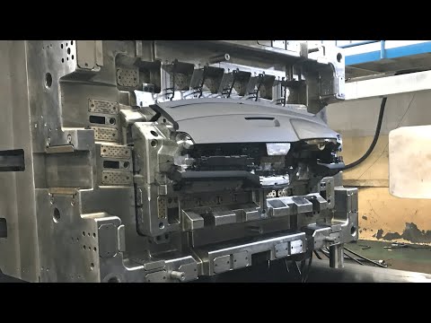
In plastic injection molding for automotive parts, mass reduction through lightweighting directly improves fuel efficiency by lowering the vehicle’s inertial load. Engineers achieve this by selecting high-strength, glass- or carbon-fiber-reinforced thermoplastics to replace denser metals, reducing component weight by up to 50% without sacrificing structural integrity. The process involves:
- Thinning wall sections via optimized mold flow analysis and ribbed geometries.
- Utilizing foaming agents (e.g., MuCell) to create a microcellular core, reducing material density.
- Replacing multi-part metal assemblies with a single, lighter injection-molded composite unit.
Each gram saved reduces the engine’s energy demand during acceleration, directly translating to lower fuel consumption per kilometer.
What Defines a High-Quality Molded Auto Component
Key Material Properties for Under-Hood Versus Interior Parts
How Wall Thickness Affects Part Strength and Cycle Time


